SHADE TREE ENGINEER
BUILDS LATHE
(article written in 2000)
Home
Gallery
Large Vase
Contact
 This
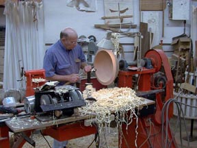
lathe was built in 1987-1988 and everything on it was shop-made, except for
motor, bearings, belts, switches. This includes the lathe itself, the spindle,
tail stock, pulleys, variable speed mechanism, and everything else. It weighs
approximately 1500 lbs., but is portable by bolting on an axle (with springs) to
the headstock, and installing a tongue to the end of the lathe. It then tows
like a trailer. I have approximately 5000 miles on my lathe.
This
lathe was built in 1987-1988 and everything on it was shop-made, except for
motor, bearings, belts, switches. This includes the lathe itself, the spindle,
tail stock, pulleys, variable speed mechanism, and everything else. It weighs
approximately 1500 lbs., but is portable by bolting on an axle (with springs) to
the headstock, and installing a tongue to the end of the lathe. It then tows
like a trailer. I have approximately 5000 miles on my lathe.
Foreground:
Variable speed grinder powered by treadmill motor. The grinding wheels turn
backward; the two wheels on the left are rubber impregnated with grit and put a
polish on the tools. But because they are rubber, you may not turn toward the
edge, but have to turn away from the edge, therefore the backward rotation.
My
boring bars are barely visible, just behind the slow-speed grinder, and to the
left and right of the wooden shelf. These bars are made from 2x2x1/4”
tube steel, and are about 8’ long. They are carried on the back (near) side of
the lathe so that they are easily put in place for use. A broad (8”x24”)
tool rest is substituted for the normal tool rest, and an auxiliary tool rest
to hold up the back of the tools is inserted into a holder which is located at
the end of the lathe (not visible). This tool rest is made from 1 1/2” angle,
and is about 4’ wide, to allow a broad swing of the tool.
Background:
On the left is a shower curtain mounted on curtain rails. Closing the
curtains contains the shavings (well, most of them) to the area just around the
lathe. This does make clean up easier.
Far right:
My tool rack is visible behind the end of the lathe. It holds almost all my
turning tools, revolves, and can be rolled to a different location. Caution is
the watchword when reaching for another tool, since the points are up. But if I
put them in point down, I have to memorize which tool goes with which handle, so
I am just careful. So far, no injuries.
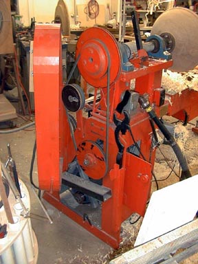 With
the belt guard open, the plywood pulleys are revealed. The darker pulleys are
the idle pulleys and are engaged by the black upward pointing handle to the
right of the belt. This is an over-center mechanism which simply snaps into
position. To change speed ranges, the handle is pulled, the belt moved to the
other pulleys, and the handle is pushed forward. Directly behind this handle is
the auxiliary switch, mounted on a magnet. This switch has a 6 foot cord attached
so it may be placed anywhere on the lathe. In front of the black
handle is the faceplate wrench, which will fit any faceplate I use.
With
the belt guard open, the plywood pulleys are revealed. The darker pulleys are
the idle pulleys and are engaged by the black upward pointing handle to the
right of the belt. This is an over-center mechanism which simply snaps into
position. To change speed ranges, the handle is pulled, the belt moved to the
other pulleys, and the handle is pushed forward. Directly behind this handle is
the auxiliary switch, mounted on a magnet. This switch has a 6 foot cord attached
so it may be placed anywhere on the lathe. In front of the black
handle is the faceplate wrench, which will fit any faceplate I use.
To
the right of the idler pulley handle is my air blower, which is nothing more
than an old vacuum cleaner motor rigged up to blow thru the hose and handle. The
handle has the switch mounted on it so it only takes one hand to turn it on. The
vacuum motor is suspended underneath the bed of the lathe. To the right of
the blower handle is the normal switch.
On
top of the lathe headstock is the handle for the brake. The brake is a wooden
sleeve epoxied to the shaft. The brake band is a piece of tin faced with leather
and tightened with the handle. In over 10 years of use, neither the brake band
or the sleeve has had to be replaced. It is effective enough that caution is
advised whenever a large piece of wood is being stopped, otherwise the spindle
will stop and unscrew the faceplate/wood.\
The
round object visible just over the belt guard is a 36” mdf jam chuck mounted
on my faceplate lathe. This lathe is capable of turning objects 6’ 4” in
diameter, although the largest I have turned was 48” (finished diameter).
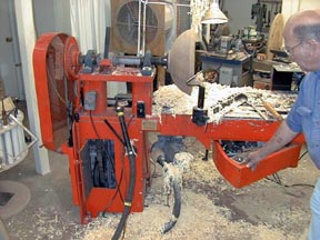 I
am opening the drawer, which is pivoted on its right front corner on 1 1/2”
ball bearings. This is the handiest thing on the lathe, and as such ends up with
all the little things that you think you need. The black handle is a rail road
spike, and to open the drawer, just push it to the right. The drawer is spring
loaded, and pops open. To close, just push it shut. The handle snaps into a hole
in the edge, and it is shut.
I
am opening the drawer, which is pivoted on its right front corner on 1 1/2”
ball bearings. This is the handiest thing on the lathe, and as such ends up with
all the little things that you think you need. The black handle is a rail road
spike, and to open the drawer, just push it to the right. The drawer is spring
loaded, and pops open. To close, just push it shut. The handle snaps into a hole
in the edge, and it is shut.
Left
background: My dust collector is visible over the headstock. This is
used only for sanding, and is on a roll-around support. When sanding, it is
moved to the back side of the lathe, just off the turning, and is very
effective. End Dust sprayed on the inside of the furnace filters makes them very
‘sticky’, and much more efficient.
The
open door under the headstock shows the variable speed mechanism. This is a
‘compound variable,’ using a double sheave and two belts. It has a 7 to 1
speed ratio. The black pipe handle pointing up to the left behind the air blower
is the speed change lever. In two ranges, the speeds are 60-420 rpm and 300-2100
rpm.
The
black knob just above and to the left of the door is a weight on my center
knock-out rod which is kept in a pipe affixed to the lathe.
The
cog gear on the end of the spindle is used to attach the plywood pulleys and
also is used as a spindle lock utilizing the yolk , the near end of which is
visible. The lock is simply pulled over and engaged with the cog gear, then when
pulled away is held by a spring catch (not visible in photo).